Exploring the MAX7219
I’ve discovered this IC completely by accident. A few years back, when working on my Kerbal Space Program visualizer, I bought a few 8x7-segment displays. They work much better than cheap HD47780s when the numbers refresh very quickly, and have distinct space machinery look that I dig. The other thing was how easy it was to drive them. They exposed just 5 pins - power and standard read-only (MOSI) SPI. On the other side of the board, the MOSI pin was “replicated” allowing daisy-chaining the units.
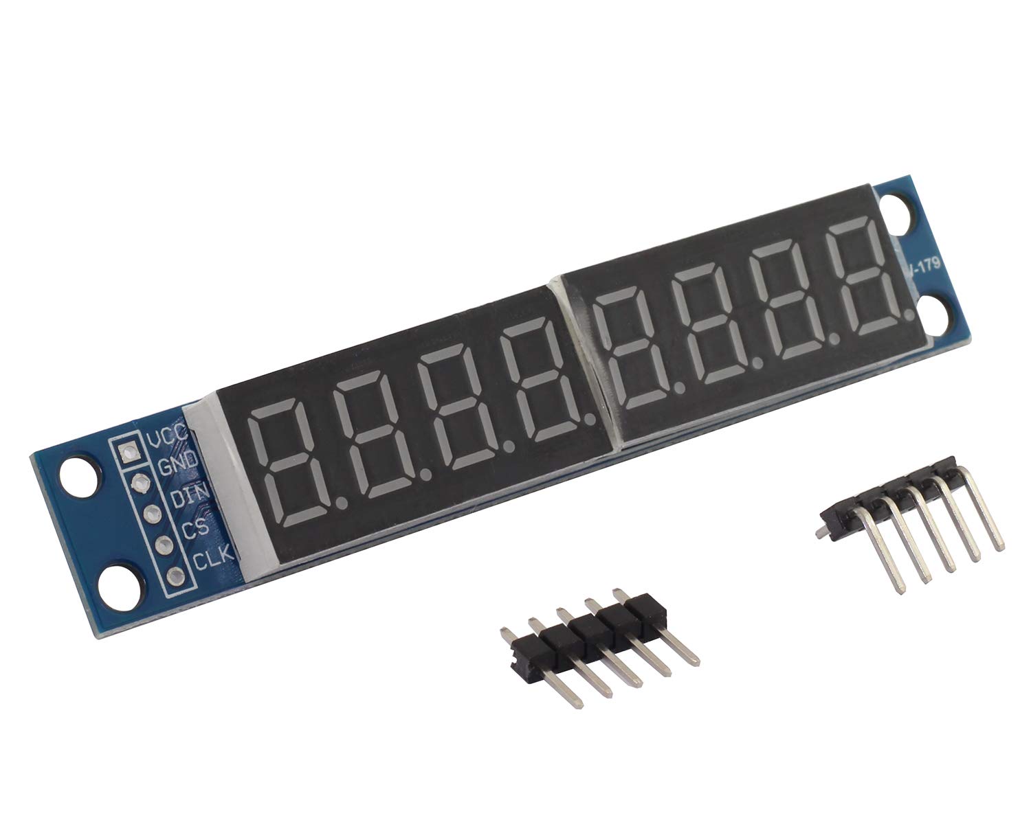
It turns out it was all possible to the small chip soldered on the other side - Maxim Integrated MAX7219CNG. I’ve been familiar with the brand, as they make the craziest stuff I’ve seen so far; they basically turn 3-month hobby project boards into ICs; so by their standards, the 7219 is actually very simple.
What it is, at least nominally, is a 7-segment or LED matrix driver, capable of displaying up to 64 bits of information. This is achieved by having 8 cathode and 8 anode lines, requiring wiring the LEDs in a matrix. For a bunch of 7-segment displays, this simply means tying the segments together, and connecting the common part of each digit to one pin of the 7219.
To aid with numerical operations, the 7219 comes with built-in data decoder, able to turn 0-16 values into corresponding 7-seg segments, with HELP letters and a few symbols left over. This works great when driving multiple 7-segments, as you can just put your data onto the ic and it’ll take care of everything.
In fact, that’s how the entire IC operates. It’s realized as a bunch of registers with some logic in between, and it’s entire “API” is just two-byte commands; the first byte (or rather 4 bits, but you send the entire byte - valued 0x0 to 0xF) determines the destination register, and the second one is the data to store. Every function of the device is controlled that way.
For most cases, it’s enough to simply “enable” the chip, disable the demo function, enable decoding and just put the digits in registers 1 through 8 (assuming you’re showing 8 digits to begin with) - it’s that simple! In fact, it really makes me wonder why anyone bothers with writing libraries for it.
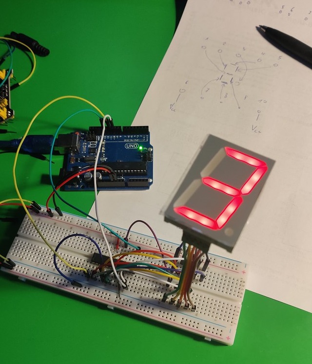
That being said, this is the “simple” path. When I ordered my batch of 7219 to have fun with, I intended to use them with my large individual 7-segs that I bought years ago. What I quickly realized, though, is that they have the inverted shared element! Instead of a common ground and a VCC for each segment, they had a common VCC and a ground for each segment. Bummer.
This meant that I won’t be able to use the decoding functionality, and think about the data in a nearly as straightforward manner. However, it’s still entirely possible to use our IC. The only thing necessary is to transpose the data so that when talking about digit X and segment Y, we actually drive digit Y and segment X. This was confirmed by a quick search on the Arduino forums:
In fact, the chip does not actually have “segment drivers” or “digit drivers” at all notwithstanding what they are called in the datasheet - it has anode drivers and cathode drivers with each cathode driver corresponding to one register in the chip, and the “Scan limit” register determining how many cathode drivers are enabled. It does not care to what you actually connect the lines as long as they connect correctly to anodes and cathodes in a matrix. source
A function realizing that could look like this:
void writeDigit(byte dig) {
    const uint8_t font[] = {
        0b01111110,
        0b00110000,
        0b01101101,
        0b01111001,
        0b00110011,
        0b01011011,
        0b01011111,
        0b01110000,
        0b01111111,
        0b01111011
    };

    for (int s = 0; s < 8; s++) {
        auto f = font[dig];
        auto b = f & (1 << (7-s));
        SpiWriteTwoBytes(s+1, b ? 0b00000001 : 0x00);
    }
}
And voila!
Here’s where the beautiful simplicity of the 7219 realizes. Since it was meant to drive LED matrices, it really doesn’t care. In fact, its use is not limited to matrices or 7-segments. As long as you have up to 64-bit LEDs which you can wire in banks of 8, you can control them with it just fine (for example, the datasheet talks about bar graph displays). You could e.g. make a 32-step stereo VU meter, or really just drive 64 LEDs in a completely arbitrary way.
All this while requiring a total of one external resistor to control the brightness of the system (the IC has further software brightness control, too!). Compared to the ratsnests people build to drive multiple LEDs out of an Arduino, it’s a total boon; just connect the LEDs to the pins and connect the SPI, and you’re done. And if 64 LEDs isn’t enough, the chip has aforementioned built-in daisy chaining, enabling you to use up to (recommended) 8 units, for a total of 512 LEDs on just three pins. (Note: you probably don’t want to be driving all that off an Arduino 5V pin, though; add a proper power supply that can handle the current.)
All in all, it’s an amazingly simple yet very clever and capable small device. With the simplicity comes the low price of about $0.40 per a DIP unit (and as usual, about half that for the SMD package).